Source Superposition & Thevenin/Norton Equivalents
BME253L - Fall 2025
Summary of Analysis Approaches (So Far)
Power Balance
KCL & KVL
Ohm’s Law
Equivalent Resistance
Voltage & Current Division
NVA & MCA
Learning Objectives
Superposition (Linear Circuits)
Thevenin Equivalent Sources (Voltage)
Norton Equivalents Sources (Current)
Superposition
In a linear circuit containing \(N\) sources, each branch voltage and current is the linear sum of \(N\) voltages and currents (i.e., each source contributes to part of the total element current and voltage).
Each source’s contribution can be calculated by “eliminating” the contribution of the other sources and solving for element currents/voltages.
“Eliminating” Sources
“Eliminating” a source means removing its voltage or current contribution to the circuit.
A voltage sourse can be eliminated by replacing it with a short circuit.
Branch current can still be conducted.
Forcing no \(\Delta\) V related to the voltage source.
A current source can be eliminated by replacing it with an open circuit.
Voltage difference allowed between two nodes.
Blocking current from flowing from other sources because the eliminated current source exclusively dictactes that branch current.
Superposition Example
Solve for \(i_3\) using source superposition.
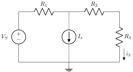
\(V_S = 10 V\)
\(R_1 = 200 \Omega\)
\(R_2 = 200 \Omega\)
\(R_3 = 100 \Omega\)
\(I_S = 0.1 A\)
\[ i_3 = i_{3_{V_S}} + i_{3_{I_S}} \]
Step 1: Eliminate \(I_S\); Solve for \(i_{3_{V_S}}\)
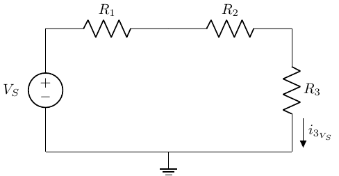
\[ i_{3_{V_S}} = \frac{V_S}{R_1+R_2+R_3} = 0.2 A \]
\(i_{3_{V_S}}\) is the contribution to total \(i_3\) from \(V_S\).
Step 2: Eliminate \(V_S\); Solve for \(i_{3_{I_S}}\)
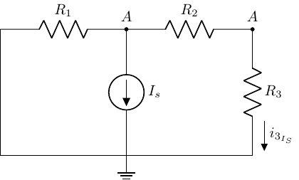
While any circuit analysis techinque we have used to date is fair game, current division resonates with me…
\[ I_{3_{I_S}} = \frac{v_A}{R_2+R_3} = -I_S\left(\frac{R_1}{R_1+R_2+R_3}\right) = -0.04 A \]
Step 3: Sum Contributions from \(I_S\) and \(V_S\)
\[ i_3 = i_{3_{V_S}} + i_{3_{I_S}} = 0.02 A + (-0.04 A) = -0.02 A \]
Let’s revisit the “super mesh” circuit…
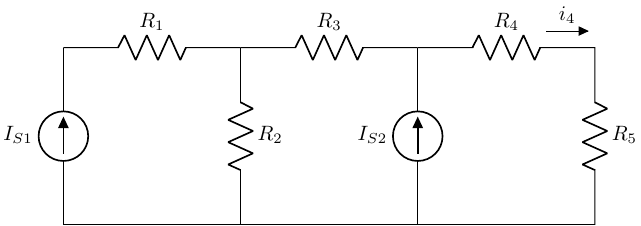
Solve for \(i_4\) using source superposition.
Let’s walk through the approach together…
Equivalent Circuits
Each “block” (physical or functional) of a circuit can be represented by a 2-terminal equivalent circuit, composed of a single source and resistance that completely captures the \(i-v\) characteristics of that block.
If that single source is a voltage source, then it is known as a Thevenin source equivalent.
If that single source is a current source, then it is known as a Norton source equivalent.
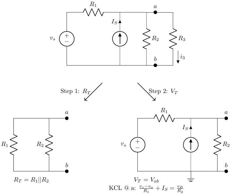
Thevenin Equivalent Sources
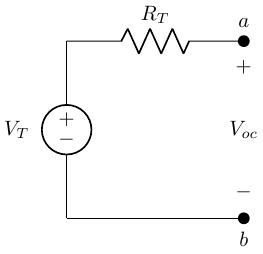
When a circuit is viewed from the perspective of the load, any source network composed of ideal voltage/current sources and linear resistors (i.e., defined by Ohm’s law), can be replaced by an equivalent circuit with:
An ideal voltage source (\(V_T\)), in series with
An equivalent resistance (\(R_T\)).
How do we solve for \(V_T\) and \(R_T\)?
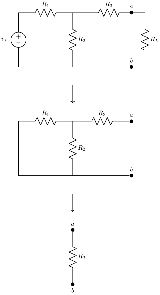
Step 1: Find the equivalent resistance
Find the equivalent resistance as “seen” by the terminals of that source block.
Remove the load from the terminals of the block.
Eliminate all independent voltage and current sources.
To date, we have only dealth with independent voltage and current sources (i.e., their source voltage or current values are not dependent on other voltages/currents in the circuit).
- Compute the equivalent resistance with the load removed.
Step 1: Example
Step 2: Find the equivalent source voltage
Solve for the equivalent Thevenin source voltage, which is equal to the terminal voltage when the terminals are “open” (i.e., no load is attached to them).
Remove the load from the terminals (create an “open” load condition).
Keep all sources.
Solve for \(V_T = V_{{ab}_{OC}}\)
Back to our example…
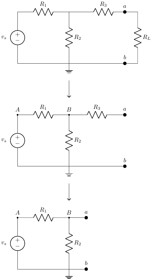
\[ V_T = V_{ab} = V_B = v_s \left(\frac{R_2}{R_1+R_2}\right) \]
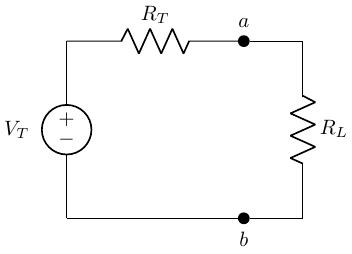
Thevenin Equivalent Circuit
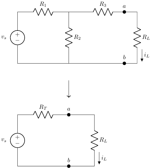
Let’s convince ourselves that \(i_L\) is the same for both circuits…
Oh wait…
I’m not going to show you this; you are going to do it!
Why use a Thevenin Equivalent Circuit?
A major benefit of using an equivalent source is that if we have an unknown or changing load (\(R_L\)), we can easily solve for \(i_L\) as a simple voltage division with known \(V_T\) and \(R_T\).
Extremely useful for instrument design!
Current draw as a function of load (e.g., make sure to not exceed \(I_{max}\) of a supply).
Power consumption as a function of load.
Another example…
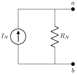
Norton Equivalent Sources
When a circuit is viewed from the perspective of the load, any source network composed of ideal voltage/current sources and linear resistors (i.e., defined by Ohm’s law), can be replaced by an equivalent circuit with:
An ideal current source (\(V_T\)), in parallel with
An equivalent resistance (\(R_N = R_T\)).
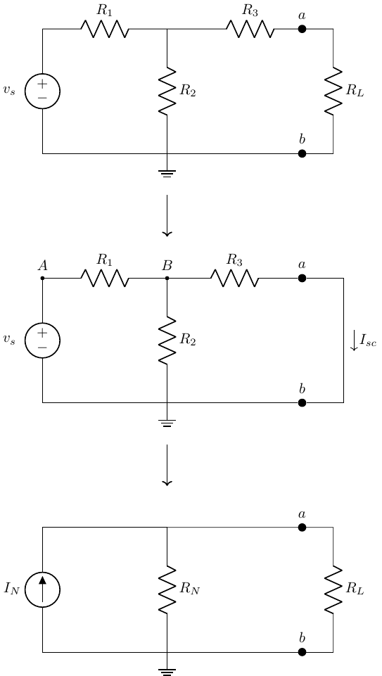
Step 1: Calculate \(R_N\)
This is the same process as calculating the Thevenin equivalent resistance (\(R_T\))!
Step 2: Calculate the Norton Equivalent Source
Similar to calculating the Thevenin equivalent source, but instead of solving for the open-circuit voltage at the terminals, solve for the short circuit current at the terminals.
This short circuit current is the Norton source current (\(I_N\)).
Proof that Thevening & Norton Equivalents Circuits are Equivalent
The circuits are equivalent if they have the same \(i-v\) characteristics.
Thevenin
\[ \begin{gather} V_L = V_T \frac{R_L}{R_T+R_L} \\ i_L = \frac{v_L}{R_L} = \frac{V_T}{R_T+R_L} \end{gather} \]
Norton
\[ \begin{gather} i_L = i_N \frac{R_T}{R_N+R_L} \\ V_L = i_L R_L = I_N R_N \frac{R_L}{R_N+R_L} \\ i_N = \frac{V_T}{R_T} \\ V_L = V_T \frac{R_L}{R_T+R_L} \end{gather} \]
They are the same!
Source Transformation
We can use these equivalent circuits to transform between voltage and current sources using Ohm’s law:
\[ V_T = I_N R_T \]
Use source transformations to change a circuit into a voltage or current division problem that is easier to solve!
Source Transformation Example
![]()
Now a simple current divider!
\[ i_4 = \left( \frac{v_1}{R_1} - I_S - \frac{v_s}{R_3} \right) \left[ \frac{\frac{1}{R_4}}{\frac{1}{R_1} + \frac{1}{R_2} + \frac{1}{R_3} + \frac{1}{R_4}}\right] \]
Maximum Power Transfer
We can use our “simple” Thevenin equivalent circuit to now represent any source:load combination.

What load resistance allows us to deliver the most power to the load?
Solve for Maximum Power Transfer
\[ \begin{gather} P_L = V_L I_L = I_L^2 R_L \\ I_L = \frac{V_T}{R_T + R_L} \\ P_L = \left( \frac{V_T}{R_T+R_L}\right)^2 R_L \\ P_L = \frac{V_T^2 R_L}{(R_T + R_L)^2} \end{gather} \]
How to Match Load and Source Resistance
If we can only adjust \(R_L\) (i.e., the source conditions are fixed), then power is maximized when:
\[ \frac{dP_L}{dR_L} = 0 \]
Maximum power is delivered to the load when \(R_T = R_L\)!!