ECAD using KiCad: SPICE Modeling
BME253L - Fall 2025
SPICE Modeling
What is SPICE?
- Simulation Program with Integrated Circuit Emphasis (SPICE)
- Model and analyze the behavior of electronic circuits before they are physically constructed.
- Input schematic representations of circuits (e.g., resistors, capacitors, transistors, diodes, etc.)
- Simulate circuit performance by computing current, voltage, and power, across these components under different conditions.
Why model circuits?
- Reduce design costs.
- Breadboards / thru-hole prototyping is not realistic for complex circuits.
- Most components are now surface mount.
- Model \(\rightarrow\) Breakout Boards \(\rightarrow\) PCB
SPICE vs. Non-SPICE Components
- SPICE components are defined by their mathematical models.
- Non-SPICE components are defined by their physical characteristics.
- KiCad has a library of SPICE models for common components.
- SPICE models are not always available for all components, but can be downloaded and added to some libraries.
- SPICE models can be edited / created for custom components.
Limiting Scope of SPICE Simulation
- We usually want to simulate as simple of a circuit as possible.
- We can limit the scope of the simulation by excluding components from the braoder schematic from the sub-circuit that we want to simulate:
- Drag select all of the components you want to exclude to highlight them.
- Right Click:
Attributes -> Exclude from Simulation - Repeat this for other sheets / circuits in the schematic.
- In the Simulation window, Confirm that your
SPICE Netlistreflets what you actually want to simulate.
Setting Component Simulation Parameters
- The SPICE model can be set in the component properties.
- The component must have a SPICE model to be included in the simulation.
- Only certain components allow certain simulation parameters to be varied (e.g., resistors vs. potentiometers).
Setting Analysis Parameters
- AC Sweep: frequency analysis
- DC Sweep: sweep voltage, current, resistance, capacitance
- Operating Point: analysis at a specific point in time
- Transient: time-domain analysis
Run Simulation and Probe Components
- Simulations are
Run(Blue Arrow in Simulation window). - Probes can be added by parameter and component name or interactively.
- Choose a
New Analysisand what components you want to sweep.- Avoid setting any values to
0as they can cause numerical instability!
- Avoid setting any values to
- After you hit
Ok, choose the parameters from the right side of the window that you would like to plot. - If you change your schematic, be sure to re-Run the simulation.
- You may want to create a new analysis tab to make sure that the simulation reflects the latest changes.
- All open analysis tabs must be valid for the running simulation to be successful!
Examples
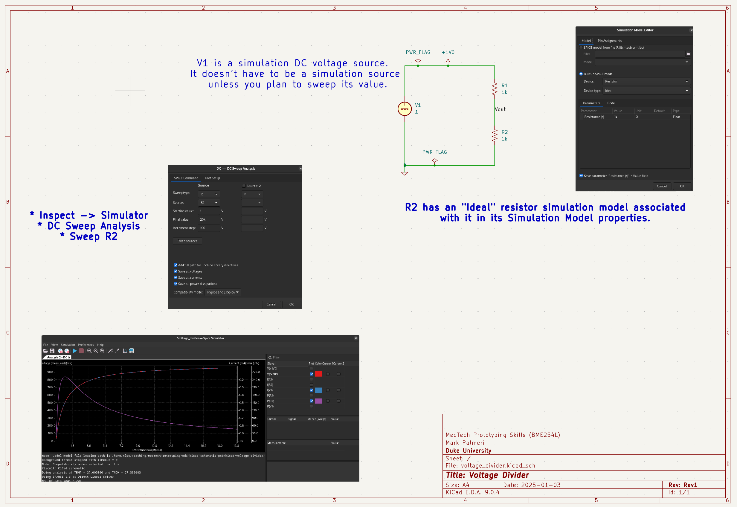
Voltage Divider with Potentiometer (DC Sweep)