Problem Set 03: Source Superposition, Thevenin & Norton Equivalent Circuits, Maximum Power Transfer
BME253L - Fall 2025
Please complete the following problems and tasks, and upload your solutions to Gradescope, using the formatting guidelines below.
Node Voltage Analysis
Solve the following problems in this section using Node Voltage Analysis.
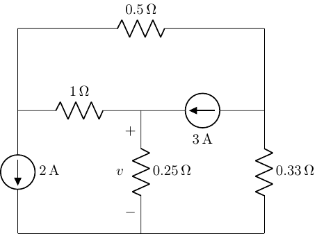
- Find voltage (\(v\)) as specified in the circuit below.
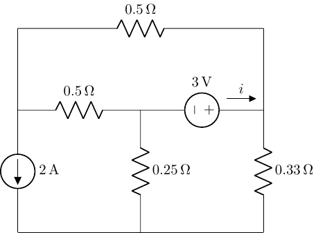
- Find the current (\(i\)) as specified in the circuit below.
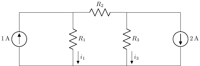
- Find the currents, \(i_1\) and \(i_3\), as specified in the circuit below, given \(R_1 = 3 \Omega\), \(R_2 = 1 \Omega\) and \(R_3 = 6 \Omega\).
Mesh Current Analysis
Solve the following problems in this section using Mesh Current Analysis.
- Find the currents, \(i_1\) and \(i_3\), as specified in the circuit below, given \(R_1 = 3 \Omega\), \(R_2 = 1 \Omega\) and \(R_3 = 6 \Omega\). (This is the same circuit analysis in problem 3 above, but solved using a different method.)
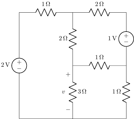
- Find the voltage (\(v\)) as specified in the circuit below.
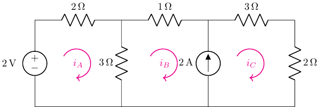
- Solve for the mesh currents \(i_A\), \(i_B\), and \(i_C\) as shown in the circuit below.
Superposition
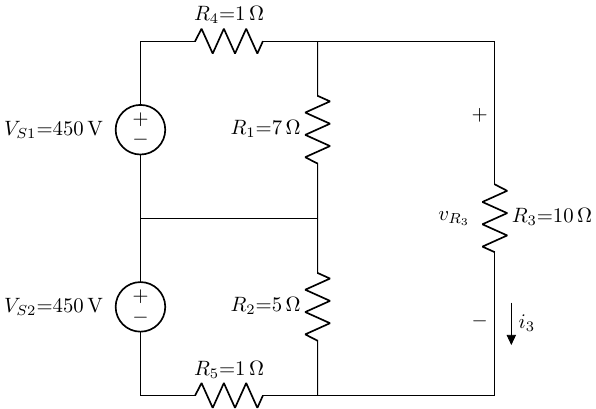
- Using superposition, solve for \(i_{R_3}\), and determine what fraction of that current comes from \(V_{S1}\) and \(V_{S2}\).
Thevenin & Norton Equivalent Circuits
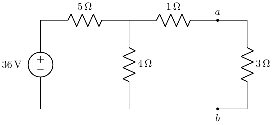
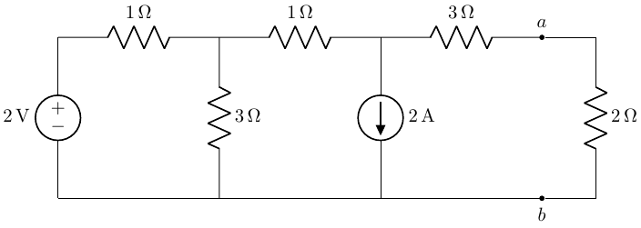
- Find the Thevenin equivalent circuit as seen by the 3 \(\Omega\) resistor in the circuit below (i.e., from the perspective of terminals \(a\) and \(b\)).
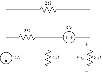
- Find \(v_{R_3}\) in the circuit below by replacing the rest of the circuit with its Thevenin equivalent.
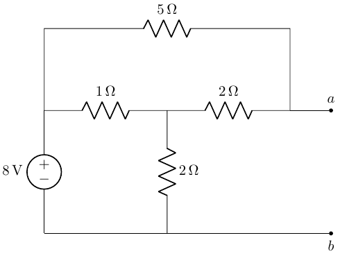
- Find the Norton equivalent circuit as seen by the 2 \(\Omega\) resistor in the circuit below (i.e., from the perspective of terminals \(a\) and \(b\)).
- Find the Norton equivalent circuit to the left of terminals \(a\) and \(b\) in the circuit below.
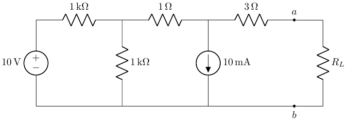
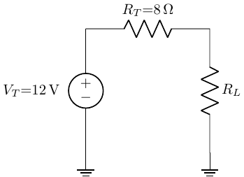
- Find the Thevenin equivalent circuit as seen by the load resistor \(R_L\) in the circuit below (i.e., from the perspective of terminals \(a\) and \(b\)).
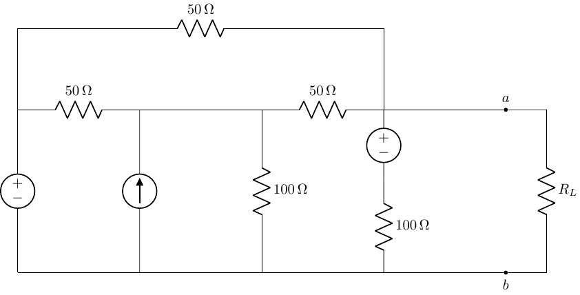
- Find the Thevenin equivalent resistance (\(R_{TH}\)) as seen by the load resistor \(R_L\) in the circuit below (i.e., from the perspective of terminals \(a\) and \(b\)).
Maximum Power Transfer
- If the conditions for maximum power transfer between the source and the load exist, determine the following:
The value of the load resistance, \(R_L\).
The power dissipated by \(R_L\).
The efficiency of the circuit (i.e., the ratio of the power dissipated by \(R_L\) to the total power supplied by the source (\(V_T\))).
- Remember that a non-ideal voltage source can be modeled as an ideal voltage source (\(V_S\))in series with a resistor (\(R_S\)). For the resistive load (\(R_L\)) shown in the circuit below:
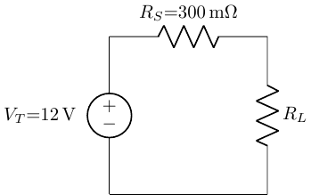
Plot the power dissipated in the load as a function of \(R_L\) for a reasonable range of \(R_L\) values.
What can you conclude from you plot in part (a) regarding the value of \(R_L\) that maximizes the power dissipated in the load and how that tapers off for lower/higher load resistances?
Prove, mathematically, that your conclusion is valid for all values of \(R_L\) and \(R_S\).
Problem Set Format Guidelines
Please follow these guidelines when completing your problem sets to insure accurate grading and to reduce time to troubleshoot problem solving.
Each problem should be on dedicated pages that will be able to be uniquely selected on Gradescope to associate with specific questions (i.e., do not have multiple problems on the same page).
For problems that involve circuit analysis, make sure that you clearly present an annotated circuit to show what variables correspond to what quantities in the analysis.
Label all circuit elements with symbols.
Solve problems symbolically before substituting in numerical values.
Please write legibly and include all relevant steps in arriving at your solution.
Please place a box around all final solutions.
All answers must have units!! No units = no credit!
Attach any computer code (e.g., Python code) used to solve problems and generate plots.
This should be done with a Jupyter notebook.
Ideally your code should “self described” your thought process, but if unclear, add comments in the code where appropriate to indicate your thought process.
All plots must be appropriately labeled with units.
Problem sets must be scanned and converted to PDFs, uploaded to Gradescope, and have each problem associated with the specific question in Gradescope.
Failure to associated pages of your PDF with specific problems in Gradescope will result in loss of credit for that question.