Problem Set 06: Operational Amplifier Circuits
BME253L - Fall 2025
Please complete the following problems and tasks, and upload your solutions to Gradescope, using the formatting guidelines below.
1. Design an Amplifier
You have an input signal described by the equation:
\[ v_{in}(t) = 0.1 \sin(2000 \pi t) \text{ V} \]
Design an operational amplifier circuit that is powered by \(\pm\) 12 V that meets the following specifications:
Gain: The output signal should have a peak voltage of 5 V.
Phase Shift: The output signal should be inverted (180-degree phase shift).
Sketch your circuit, labeling all relevant components and their values.
Derive the expression for the output voltage \(v_{out}(t)\).
Plot both the input and output signals over 5 periods of the input signal. Be sure to label your axes, including units.
2. Input Impedance
Describe why we typically want the input impedance of an op-amp circuit to be very high.
What is the input impedance of your circuit from Problem 1?
If the input impedance of your circuit from Problem 1 isn’t “ideal” given the considerations you described in part (a), suggest a modification to your circuit that would improve the input impedance.
3. Op-Amp Saturation
You have an input signal described by the equation:
\[ v_{in}(t) = 0.2 \cos(1000 \pi t) \text{ V} \]
What is the maximum gain that you can achieve with a single op-amp stage powered by \(\pm\) 12 V without clipping the output signal?
4. DC Offset
You have an input signal described by the equation:
\[ v_{in}(t) = 0.05 \sin(500 \pi t) + 0.5 \text{ V} \]
Design an operational amplifier circuit powered by \(\pm\) 12 V that creates an output signal described by the equation:
\[ v_{out}(t) = 2 \sin(500 \pi t) \text{ V} \]
Note the phase of the output signal relative to the input signal. You can use more than one op-amp stage if necessary.
Sketch your circuit, labeling all relevant components and their values.
For your design, how much power does your \(v_{in}(t)\) signal source deliver if your overall circuit is driving a load of 100 k\(\Omega\)?
5. Differential Amplifier
For the differential amplifier circuit that was presented in lecture, we make an assumption that \(R_1 = R_2\) and \(R_3 = R_4\).
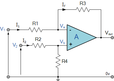
If \(R_2 = (1\pm0.1)R_1\) and \(R_4 = (1\pm0.1)R_3\), meaning that the resistors can vary by as much as 10% from their nominal values, what is the maximum possible error in the output voltage \(V_{out}\) when the input voltages are \(V_1 = 2\) V and \(V_2 = 1\) V? Assume that \(R_1 = R_3 = 10\) k\(\Omega\).