Op Amps: Amplifiers & Active Filers
BME253L - Fall 2025 - Palmeri
Objectives
Build and analyze inverting and non-inverting amplifiers, characterizing:
Gain,
Phase shift, and
Saturation.
Build and analyze an active low-pass filter.
Build and analyze a summing amplifier.
Background
Please review all of the lecture content on operational amplifiers.
Procedure
1. Inverting Amplifier
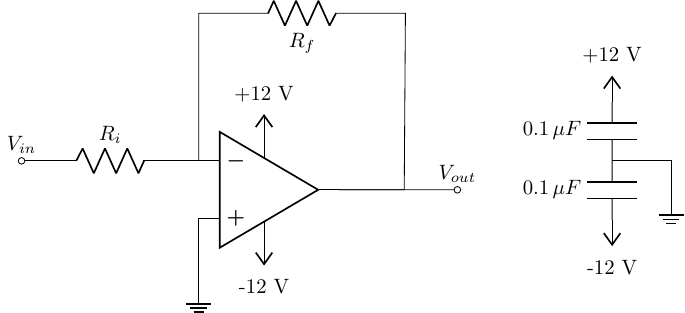
Build the circuit above.
Use \(R_i\) = 2.7 kΩ, \(R_f\) = 4.7 kΩ.
The input should be a 0.1 \(V_{pp}\) sine wave at 1 kHz.
The op-amp should be powered with ±12 V.
The \(0.1 \mu F\) capacitors are for power supply decoupling, which helps stabalize the power supply lines to the chip.
You should have these capacitors physically be as close to the op-amp power pins as possible.
The pin-out for the DIP-8 package for this chip is available in the datasheet.
Opamps are active devices and must always have a source of power. Many schematics, including those that follow in this course, omit the power supply connections because they are assumed.
Opamps can be damaged by applying the wrong voltages to terminals. A good idea is to build the circuit with the power supply output turned off. When you turn on the power supply, check the supply voltages and currents. If they don’t look correct, turn off the power supply output until you’ve corrected your problem. Each LF353 opamp should draw about 4 mA from each supply.
Experimentally determine the voltage gain of this inverting circuit by capturing both the input and output signals on your oscilloscope and showing relevant measurements.
What is the phase relationship between the input and output signals, and how does this compare to the nominal value?
Compare the experimentally determined gain with the nominal values from the components in your circuit. Discuss any differences.
Replace \(R_f =100\,k\Omega\) and calculate the nominal and experimentally-measured voltage gains. Again, discuss any differences.
For \(R_f = 100\,k\Omega\), what is the maximum input voltage amplitude you can apply before the output signal becomes saturated? Explain why this happens.
Demonstrate saturation on your oscilloscope by adjusting the input voltage amplitude to 10% greater than the threshold you specified in the previous step.
2. Non-Inverting Amplifier
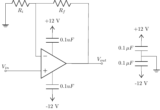
Build the circuit above.
Apply a 0.1 \(V_{pp}\), 1 kHz sine wave to the input.
Let \(R_i = 560\,\Omega\) and \(R_f = 150\,\Omega\).
Experimentally determine the voltage gain of this inverting circuit by capturing both the input and output signals on your oscilloscope and showing relevant measurements.
What is the phase relationship between the input and output signals, and how does this compare to the nominal value?
Compare the experimentally determined gain with the nominal values from the components in your circuit. Discuss any differences.
Replace \(R_f =1\,k\Omega\) and calculate the nominal and experimentally-measured voltage gains. Again, discuss any differences.
For \(R_f = 1\,k\Omega\), what is the maximum input voltage amplitude you can apply before the output signal becomes saturated? Explain why this happens.
Demonstrate saturation on your oscilloscope by adjusting the input voltage amplitude to 10% greater than the threshold you specified in the previous step.
3. Active Low-Pass Filter
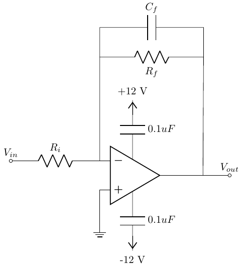
- Build the circuit above.
\(R_f = R_i~= 3.3\,k\Omega\) and \(C_f = 470\,nF\).
Use the function generator to apply a 1 \(V_{pp}\) sine wave at 1 kHz.
This circuit sometimes misbehaves when it does not have proper decoupling capacitors. Have the lab staff check your circuit and tell you about decoupling capacitors after you build this circuit.
Sketch the magnitude and phase Bode plots for this circuit, annotating all important features and taking care to label the axes appropriately.
Capture a screenshot of the circuit’s input and output signals.
Change the input signal to a 1 \(V_{pp}\) triangular wave at 1 kHz. Capture a screenshot of the circuit’s input and output signals.
Change the input signal to a 1 \(V_{pp}\) square wave at 1 kHz. Capture a screenshot of the circuit’s input and output signals.
Comment on the relationship between input and output voltages. Explain what you observe.
Repeat all of the input waveforms (sine, triangle, square) at 100 Hz. Capture screenshots of the circuit’s input and output signals for each waveform and comment on the relationship between input and output voltages. Explain what you observe, and compare/contrast with the 1 kHz waveform and your insights in this circuit acting as an active low-pass filter.
4. Summing Amplifier
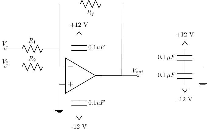
Build the circuit above.
\(R_1 = R_2 = R_f = 10\,k\Omega\).
The op-amp should be powered with ±12 V.
Apply a 0.25 \(V_{pp}\), 1 kHz sine wave to the input \(V_1\) and +0.25 V (DC) to input \(V_2\).
Capture a screenshot of the circuit’s sinusoidal input and output signals.
Derive the expected output voltage expression based on the input voltages and resistor values to confirm your experimental results. Note both amplitudes and phase.
Without changing the input voltage signals, change the values of \(R_1\), \(R_2\), and/or \(R_f\) to achieve an output signal of \(V_{out} = 0.5 \sin(2 \pi 1000 t + \pi) + 0.5 V\).
Capture a screenshot of the output signal.
Show your calculations using these new resistor values to confirm your experimental results.