Problem Set 05: Phasors & RCL Circuits
BME253L - Fall 2025
Please complete the following problems and tasks, and upload your solutions to Gradescope, using the formatting guidelines below.
Time-Dependent Signal Sources
- Find the average and RMS values of \(x(t) = 2 \cos(\omega t) + 2.5\).
Phasors and Complex Numbers
Find the phasor form of the following functions:
\(v(t) = 155 \cos(377t - 25^\circ)\) V
\(v(t) = 5 \sin(1,000t - 40^\circ)\) V
\(i(t) = 10 \cos(10t + 630^\circ) + 15 \cos(10t - 420^\circ)\) A
\(i(t) = 460 \cos(500 \pi t - 250^\circ) - 220 \sin(500 \pi t + 15^\circ)\) A
Convert the following complex numbers to polar form:
\(4 + j4\)
\(-3 + j4\)
\(j + 2 -j4 -3\)
Given \(v_1(t) = 10 \cos(\omega t + 30^\circ)\) V and \(v_2(t) = 20 \cos(\omega t + 60^\circ)\) V, find \(v(t) = v_1(t) + v_2(t)\) using:
Time-domain analysis / trigonometric identities
Phasor-domain analysis
Phasor Circuit Analysis
If the current and voltage across a component are given by \(i(t) = 17 \cos(\omega t - \pi / 12)\) A and \(v(t) = 3.5 \cos(\omega t + 1.309)\) V, where \(\omega = 628.3\) rad/s, determine:
Is the component a resistor, inductor, or capacitor?
The value of the component in its appropriate units.
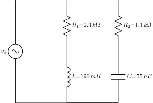
- Determine the equivalent impedance of the circuit shown below, where \(v_s(t) = 636 (3,000 t + \pi / 12)\) V.
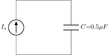
In the circuit below, \(i_s(t) = I_o \cos(\omega t + \pi/6)\), where \(\omega = 1,000\) rad/s and \(I_o = 13\) mA.
State, using phasor notation, the source current.
Determine the impedance of the capacitor.
Using only phasor notation, determine the voltage across the capacitor, including its polarity.
KiCad/SPICE
- Simulate the circuit shown below.
![]()
a. AC Frequency Analysis
Use
VSINfor the voltage source.Be sure to define the SPICE-specific
0ground (reference) node, and add the \(V_{out}\) net label.Set all of the component values as shown in the schematic.
Run the
Simulatorto perform aSmall-signal Analysis (AC)using the following parameters:Points per decade: 100
Start frequency: 10 Hz
Stop frequency: 1 MHz
Plot the magnitude and phase of the output voltage \(V_{out}\).
b. Transient Analysis
Use the Transient Analysis to show the sinusoidal waveforms of both voltage and current through time through the capacitor.
Set the
VSINsource to have an amplitude of 12 V and a frequency of 120 kHz.Run the
Simulatorto perform aTransient Analysisusing the following parameters:Time Step: 1 \(\mu\)s
Start Time: 0 s
Stop Time: 50 \(\mu\)s
Plot the voltage across the capacitor \(V_{out}\) and the current through the capacitor \(I_{C_1}\).
Problem Set Format Guidelines
Please follow these guidelines when completing your problem sets to insure accurate grading and to reduce time to troubleshoot problem solving.
Each problem should be on dedicated pages that will be able to be uniquely selected on Gradescope to associate with specific questions (i.e., do not have multiple problems on the same page).
For problems that involve circuit analysis, make sure that you clearly present an annotated circuit to show what variables correspond to what quantities in the analysis.
Label all circuit elements with symbols.
Solve problems symbolically before substituting in numerical values.
Please write legibly and include all relevant steps in arriving at your solution.
Please place a box around all final solutions.
All answers must have units!! No units = no credit!
Attach any computer code (e.g., Python code) used to solve problems and generate plots.
This should be done with a Jupyter notebook.
Ideally your code should “self described” your thought process, but if unclear, add comments in the code where appropriate to indicate your thought process.
All plots must be appropriately labeled with units.
Problem sets must be scanned and converted to PDFs, uploaded to Gradescope, and have each problem associated with the specific question in Gradescope.
Failure to associated pages of your PDF with specific problems in Gradescope will result in loss of credit for that question.