KiCad: Schematic Capture & SPICE Simulation
BME253L - Fall 2025 - Palmeri
Learning Objectives
- Create a schematic in KiCad
- Annotate and assign component values
- Set up and run a SPICE simulation
- Analyze simulation results
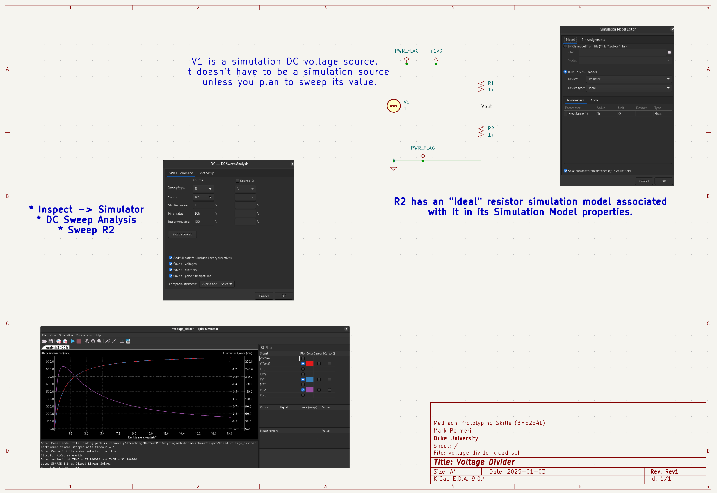
Voltage Divider Circuit
Capture the Schematic
- Create a new KiCad project.
- Fill in the schematic metadata that is populated in the right foot of the sheet.
- Create the circuit shown below using the schematic editor. Note that all of the sources chosen are SPICE DC sources.
Upload a screenshot of your complete schematic window to Gradescope.
Simulate Maximum Power Transfer
In a recent problem set, you analytically solved for the load resistance that maximizes power transfer in a voltage divider circuit. In this section, you will simulate the same circuit in KiCad and verify your results.
- Sweep the value of \(R_2\) (representing the load resistance) from 0.1 to 10k\(\Omega\) in increments of 100\(\Omega\), for a fixed \(R_1\) of 1k\(\Omega\) (representing the source resistance).
- Plot the power dissipated in \(R_2\) as a function of \(R_2\) and identify the value that maximizes power transfer.
Upload a screenshot of your swept resistance plot demonstrating maximum power transfer to Gradescope.
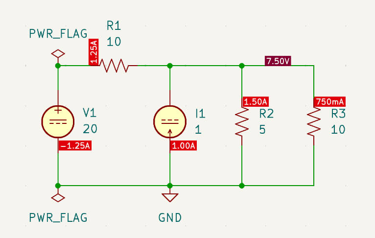
Multi-Source Circuit
The circuit shown below was one of the problems in your recent exam.
Capture the Schematic
- Create a new KiCad project.
- Fill in the schematic metadata that is populated in the right foot of the sheet.
- Create the circuit shown below using the schematic editor. Note that all of the sources chosen are SPICE DC sources.
Upload a screenshot of your complete schematic window to Gradescope.
Simulate the Operating Point (OP) Analysis
- Operating Point simulations are appropriate for circuits that have DC sources and single-valued element current / voltage values.
- Run an OP simulation for this circuit and verify your results, as shown annoted in the circuit above and summarized below.
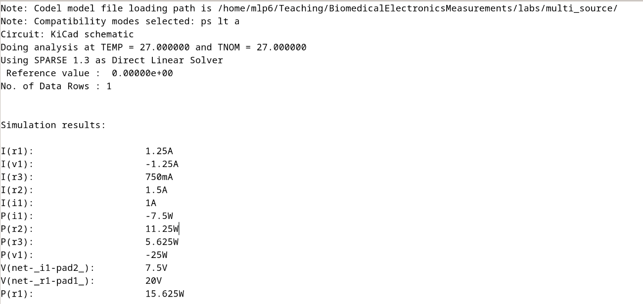
Upload a screenshot of your operating point (OP) simulation results to Gradescope.
Simulate DC Sweeps
- Perform a new analysis that sweeps several components over a range of values:
- Sweep \(V_1\) from 1 to 10 V in increments of 0.2 V
- Sweep \(I_1\) from 1 to 5 A in increments of 0.2 A
- Plot:
- \(I_{R_2}\)
- \(P_{V_1}\)
- \(P_{I_1}\)
You should see results similar to those shown below.
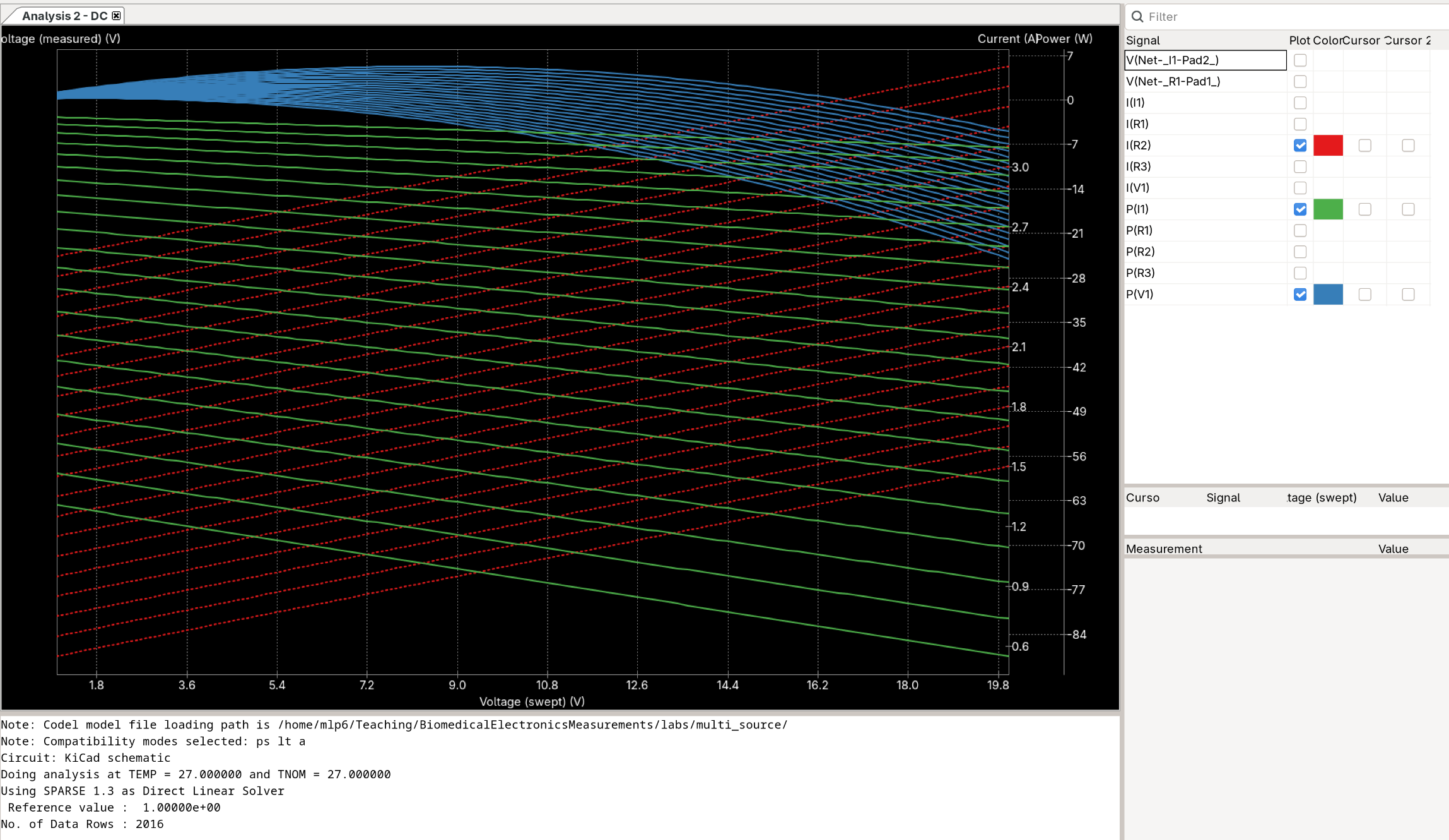
Upload a screenshot of your DC sweep simulation results to Gradescope.