Problem Set 02
BME253L - Fall 2025
Please complete the following problems and tasks, and upload your solutions to Gradescope, using the formatting guidelines below.
You are asked to generate plots and include the code that you wrote to do so in some of the problems below. Presenting your code with your plot may be most easily done using a Jupyter notebook, where you can render your output as a PDF for upload to Gradescope. This is a good opportunity to make sure you know how to do this.
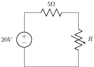
Variable Resistor / Potentiometer: For the circuit below, determine the power absorbed by the variable resistor (\(R\)), ranging from 0-20 \(\Omega\). Plot the power absorption as a function of \(R\). Your plot should be generated “formally” using Python (i.e., not hand-drawn). Include your code with your plot.
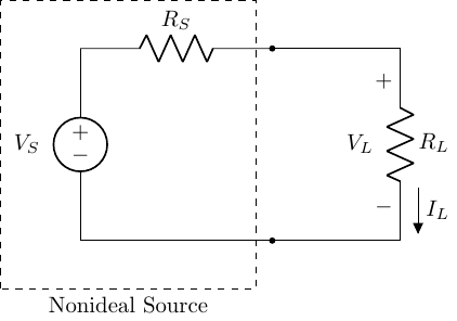
Internal Source Resistance: For the circuit below, solve for the following:
Find the total power supplied by the ideal source. (Hint: that implies the value of \(R_S\).)
Find the power dissipated and lost in the nonideal source.
What is the power supplied by the source to the circuit as a function of the load resistance (\(R_L\))?
Plot the voltage across the load \(V_L\) and the power delivered to the load (\(P_L\)) as a function of current \(I_L: 0-30 A\), assuming \(V_S = 12\,V\) and \(R_S = 0.3\,\Omega\). (Like the previous problem, include code and plot.)
Series Resistance: An incandescent lightbult rated at 100 W will dissipate 100 W as heat and light when connected to a 100 V ideal voltage source. If 3 of these bulbs are connected in series across this same source, determine the power that each bulb will dissipate.
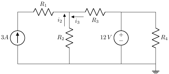
Circuit Analysis: For the circuit below, with \(R_1 = 25\,\Omega\), \(R_2 = 10\,\Omega\), \(R_3 = 5\,\Omega\), \(R_4 = 7\,\Omega\), find:
The currents \(i_2\) and \(i_3\).
The power delivered by the 3 A current soruce and by the 12 V voltage source.
The total power dissipated by the circuit.
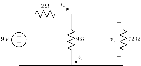
Equivalent Resistance: Find the equivalent resistance seen by the source in the circuit below and use the result to solve for \(i_1\), \(i_2\) and \(v_3\).
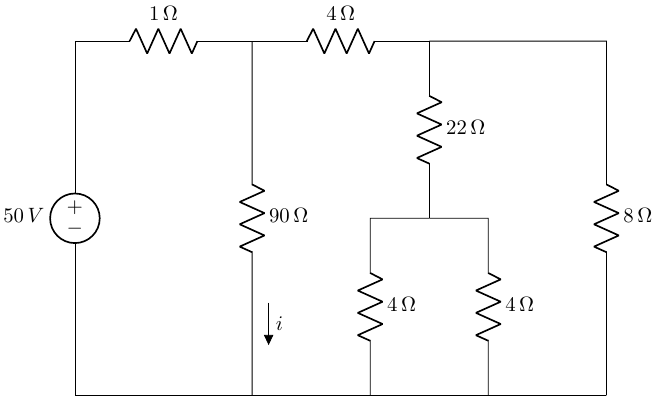
Equivalent Resistance: For the circuit below, solve for the equivalent resistance seen by the source and solve for \(i\).
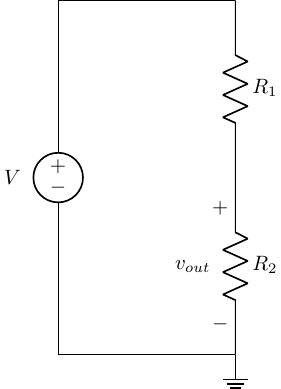
Voltage Division: The voltage divider shown below nominally provides \(v_{out} = 5\,V\) for a source voltage of \(V = 10\,V\). The resistors are nominally each \(5\,k\Omega\), but their finite tolerances mean they might not be exactly the same.
If the resistors have \(\pm\) 10% tolerance, find the “worst-case” output voltages (i.e., greatest deviations greater than and less than \(5\,V\)).
Repeat (a) for \(\pm\) 5% tolerances.
Thermistor: A thermistor is a nonlinear device that changes resistance as a function of its temperature. The relationship between resistance and temperature is:
\[ R_{th}(T) = R_o e^{-\beta(T-To)}, \]
\(R_{th}\) = resistance at temperature \(T\) (\(\Omega\))
\(R_o\) = resistance at \(T_o\) = 298 \(K\)
\(\beta\) = material constant (\(K^{-1}\))
\(T\) = absolute temperature (\(K\))
If \(R_o = 300 \Omega\) and \(\beta = 0.01 K^{-1}\), plot \(R_{th}(T)\) as a function of \(350 \leq T \leq 750\).
If the thermistor is in parallel with a fixed value \(250 \Omega\) resistor, find the expression for the equivalent resistance for this resistive network and add a new line to your plot from (a) representing the modified \(R_{th}(T)\). Be sure to plot this line in a new color and include a descriptive legend on your plot.
Material Conductance Copper and nickel-chromium (“nichrome”) are two common conductors you will find in your living space.
Where do you commonly find these two conductors in your living space, and what are the properties of these conductors that make them appropriate for their application(s)?
Aluminum is another common conductor user in high voltage transmission lines and high power household appliance wires. Why would aluminum be considered over copper for these applications?
Why isn’t aluminum wiring used instead of copper in wiring most building outlets and lighting circuits?
Material properties to keep in mind when answering these questions including resistivity, melting point, thermal expansion, and density.
Problem Set Format Guidelines
Please follow these guidelines when completing your problem sets to insure accurate grading and to reduce time to troubleshoot problem solving.
Each problem should be on dedicated pages that will be able to be uniquely selected on Gradescope to associate with specific questions (i.e., do not have multiple problems on the same page).
For problems that involve circuit analysis, make sure that you clearly present an annotated circuit to show what variables correspond to what quantities in the analysis.
Label all circuit elements with symbols.
Solve problems symbolically before substituting in numerical values.
Please write legibly and include all relevant steps in arriving at your solution.
Please place a box around all final solutions.
All answers must have units!! No units = no credit!
Attach any computer code (e.g., Python code) used to solve problems and generate plots.
This should be done with a Jupyter notebook.
Ideally your code should “self described” your thought process, but if unclear, add comments in the code where appropriate to indicate your thought process.
All plots must be appropriately labeled with units.
Problem sets must be scanned and converted to PDFs, uploaded to Gradescope, and have each problem associated with the specific question in Gradescope.
Failure to associated pages of your PDF with specific problems in Gradescope will result in loss of credit for that question.