Operational Amplifiers (Op-Amps)
BME253L - Fall 2025
Overview
Operational Amplifiers (Op-Amps) are fundamental building blocks in analog electronics.
They are used in various applications such as amplification, filtering, and mathematical operations, such as “comparison”.
They are characterized by high gain, high input impedance, and low output impedance. Their application as a buffer is particularly important in preventing signal loading.
They can be used in both open-loop and closed-loop configurations.
With negative feedback, they can achieve precise gain control and stability.
With positive feedback, they can be used in applications like oscillators and comparators.
They can perform mathematical operations such as addition, subtraction, integration, and differentiation.
Background
Credit: Many images from Electronics Tutorials website.
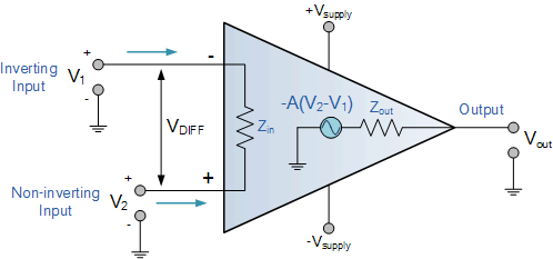
Ideal Op-Amp Model
An ideal op-amp has the following characteristics:
Infinite open-loop gain (A → ∞)
Infinite input impedance (\(Z_{in}\) → ∞)
Zero output impedance (\(Z_{out}\) = 0)
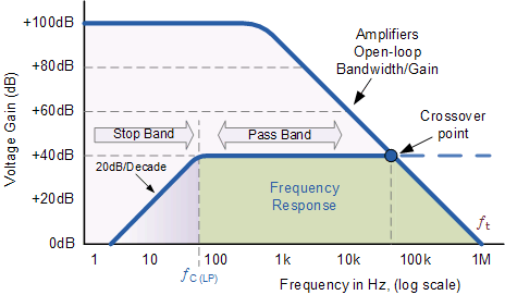
Infinite bandwidth (no frequency dependence)
Zero offset voltage (output is zero when inputs are equal)
- In practical applications, real op-amps deviate from these ideal characteristics, but the ideal model provides a useful approximation for analysis.
Voltage Saturation
Real op-amps have power supply limits that constrain the output voltage range.
When the output voltage exceeds these limits, the op-amp saturates, resulting in distortion of the output signal.
Saturation can be mitigated by ensuring that the input signals and feedback network are designed to keep the output within the linear operating range of the op-amp.
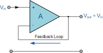
Buffer / Voltage Follower
A buffer, or voltage follower, is a configuration where the output voltage directly follows the input voltage.
It is used to isolate different stages of a circuit, preventing loading effects and ensuring signal integrity.
The voltage follower has a gain of 1 (unity gain) and provides high input impedance and low output impedance.
Negative Feedback
Negative feedback occurs when a portion of the output signal is fed back to the inverting input of the op-amp.
This configuration stabilizes the gain and improves linearity.
It can also reduce distortion and increase bandwidth.
Negative feedback means that the op-amp will adjust its output to minimize the difference between the inverting and non-inverting inputs.
\[ v_+ = v_- \]
Buffer Operation
\(V_-\) is connected to \(V_{out}\), so the op-amp adjusts \(V_{out}\) to make \(V_+ = V_-\).
\(V_{out} = V_{in}\).
\(I_{in} = 0\) (ideal op-amp input current).
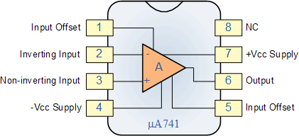
Op-Amp Chip Pinout
Amplifiers
Inverting Amplifier
Non-inverting Amplifier
Summing Amplifier
Differential Amplifier
Instrumentation Amplifier
Inverting Amplifier

Using negative feedback, the op-amp adjusts \(V_{out}\) to make \(V_+ = V_-\).
Since \(V_+ = 0V\) (grounded), \(V_- = 0V\).
Using Ohm’s Law and Kirchhoff’s Current Law (KCL):
\(I_{in} = \frac{V_{in} - V_-}{R_{in}} = \frac{V_{in}}{R_{in}}\)
\(I_{f} = \frac{V_- - V_{out}}{R_f} = \frac{-V_{out}}{R_f}\)
Since \(I_{in} = I_{f}\) (no current into op-amp input):
\[ \begin{gather} \frac{V_{in}}{R_{in}} = \frac{-V_{out}}{R_f} \\ \frac{V_{out}}{V_{in}} = -\frac{R_f}{R_{in}} \end{gather} \]
Gain is controlled by the ratio of resistors (until saturation).
The negative sign indicates a 180-degree phase shift between input and output.
Non-Inverting Amplifier

Using negative feedback, the op-amp adjusts \(V_{out}\) to make \(V_+ = V_-\).
Since \(V_+ = V_{in}\), \(V_- = V_{in}\).
Using Ohm’s Law and Kirchhoff’s Current Law (KCL):
\(I_{f} = \frac{V_- - V_{out}}{R_f} = \frac{V_{in} - V_{out}}{R_f}\)
\(I_{g} = \frac{V_{-} - 0V}{R_g} = \frac{V_{in}}{R_g}\)
Since \(I_{f} = I_{g}\) (no current into op-amp input):
\[ \begin{gather} \frac{V_{in} - V_{out}}{R_f} = \frac{V_{in}}{R_g} \\ \frac{V_{out}}{V_{in}} = 1 + \frac{R_f}{R_g} \end{gather} \]
Gain is controlled by the ratio of resistors plus one (until saturation).
The output is in phase with the input.
Summing Amplifier
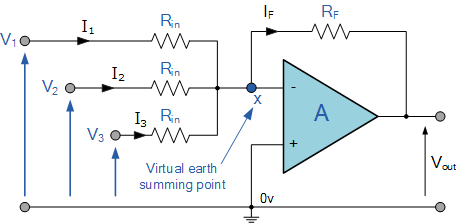
Using negative feedback, the op-amp adjusts \(V_{out}\) to make \(V_+ = V_-\).
Since \(V_+ = 0V\) (grounded), \(V_- = 0V\).
Using Ohm’s Law and Kirchhoff’s Current Law (KCL):
\(I_{1} = \frac{V_{in1} - V_-}{R_{1}} = \frac{V_{in1}}{R_{1}}\)
\(I_{2} = \frac{V_{in2} - V_-}{R_{2}} = \frac{V_{in2}}{R_{2}}\)
\(I_{f} = \frac{V_- - V_{out}}{R_f} = \frac{-V_{out}}{R_f}\)
Since \(I_{1} + I_{2} = I_{f}\) (no current into op-amp input):
\[ \begin{gather} \frac{V_{in1}}{R_{1}} + \frac{V_{in2}}{R_{2}} = \frac{-V_{out}}{R_f} \\ V_{out} = -R_f \left( \frac{V_{in1}}{R_{1}} + \frac{V_{in2}}{R_{2}} \right) \end{gather} \]
The output voltage is the negative weighted sum of the input voltages.
Differential Amplifier
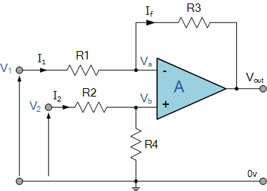
Using negative feedback, the op-amp adjusts \(V_{out}\) to make \(V_+ = V_-\).
Using Ohm’s Law and Kirchhoff’s Current Law (KCL):
For the non-inverting input:
\[ V_+ = V_2 \frac{R_4}{R_2 + R_4} \]
For the inverting input:
\[ \begin{gather} I_1 = I_f \\ \frac{V_1 - V_-}{R_1} = \frac{V_- - V_{out}}{R_3} \\ \end{gather} \]
If we set \(R_1 = R_2\) and \(R_3 = R_4\), solving for \(V_{out}\):
\[ V_{out} = \frac{R_3}{R_1} (V_2 - V_1) \]
The output voltage is the amplified difference between the two input voltages.
Instrumentation Amplifier
Active Filters
“Active” filters use op-amps to provide the possibility for gain \(>\) 0 dB, along with resistors and capacitors to achieve desired frequency response characteristics
Same “rules” for analyzing op-amp circuits with negative feedback apply, along with those for first-order filters.
Active Low-Pass Filter
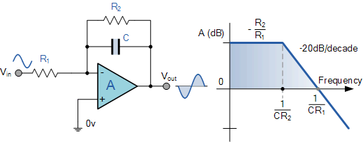
D.C. Gain: \(\frac{-R_2}{R_1}\)
A.C. Gain: \(\frac{-R_2}{R_1} \frac{1}{1+\omega R_2 C}\)
Cutoff Frequency: \(\omega_c = \frac{1}{R_2 C}\)
KiCad SPICE: Active Low-Pass Filter
In-class demo…
Active High-Pass Filter

Active Band-Pass Filter
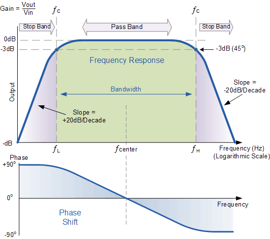
D.C. Gain: \(\frac{-R_2}{R_1}\)
\(\omega_{HP} = \frac{1}{R_1 C_1}\)
\(\omega_{LP} = \frac{1}{R_2 C_2}\)
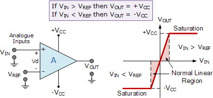
Comparator
A comparator is a device that compares two voltages or currents and outputs a digital signal indicating which is larger.
It lacks negative feedback, resulting in a high gain that drives the output to saturation.
Comparator with Hysteresis (Schmitt Trigger)
