Source Superposition & Thevenin/Norton Equivalents
BME253L - Fall 2025
September 10, 2025
Superposition Example
Note
Solve for \(i_3\) using source superposition.
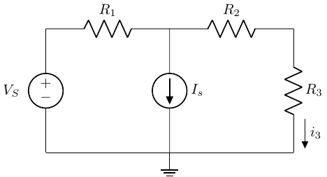
\(V_S = 10 V\)
\(R_1 = 200 \Omega\)
\(R_2 = 200 \Omega\)
\(R_3 = 100 \Omega\)
\(I_S = 0.1 A\)
Note
\[ i_3 = i_{3_{V_S}} + i_{3_{I_S}} \]
Step 1: Eliminate \(I_S\); Solve for \(i_{3_{V_S}}\)
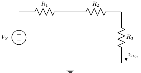
\[ i_{3_{V_S}} = \frac{V_S}{R_1+R_2+R_3} = 0.2 A \]
Note
\(i_{3_{V_S}}\) is the contribution to total \(i_3\) from \(V_S\).
Step 2: Eliminate \(V_S\); Solve for \(i_{3_{I_S}}\)
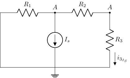
Tip
While any circuit analysis techinque we have used to date is fair game, current division resonates with me…
\[ I_{3_{I_S}} = \frac{v_A}{R_2+R_3} = -I_S\left(\frac{R_1}{R_1+R_2+R_3}\right) = -0.04 A \]
Step 3: Sum Contributions from \(I_S\) and \(V_S\)
\[ i_3 = i_{3_{V_S}} + i_{3_{I_S}} = 0.02 A + (-0.04 A) = -0.02 A \]
Let’s revisit the “super mesh” circuit…
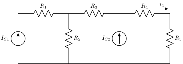
Solve for \(i_4\) using source superposition.
Let’s walk through the approach together…
Thevenin Equivalent Sources
Thevenin Theorem
When a circuit is viewed from the perspective of the load, any source network composed of ideal voltage/current sources and linear resistors (i.e., defined by Ohm’s law), can be replaced by an equivalent circuit with:
An ideal voltage source (\(V_T\)), in series with
An equivalent resistance (\(R_T\)).
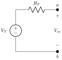
How do we solve for \(V_T\) and \(R_T\)?
Step 1: Example
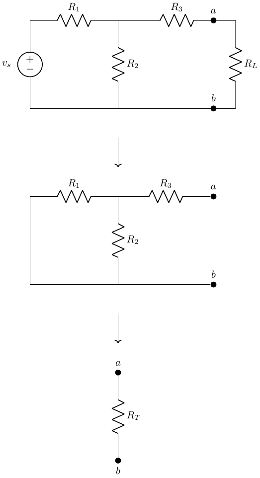
Back to our example…
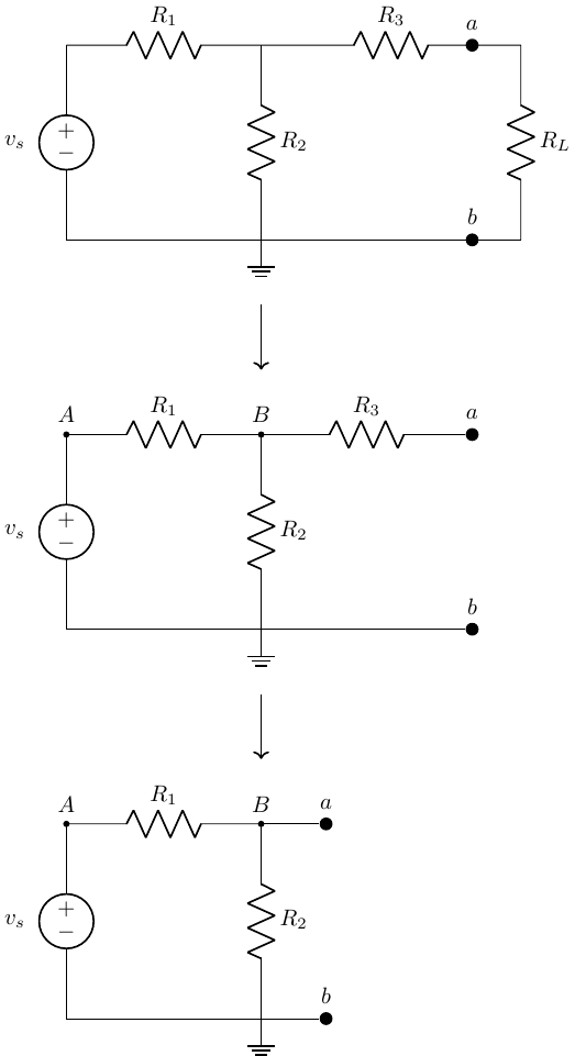
\[ V_T = V_{ab} = V_B = v_s \left(\frac{R_2}{R_1+R_2}\right) \]
Thevenin Equivalent Circuit
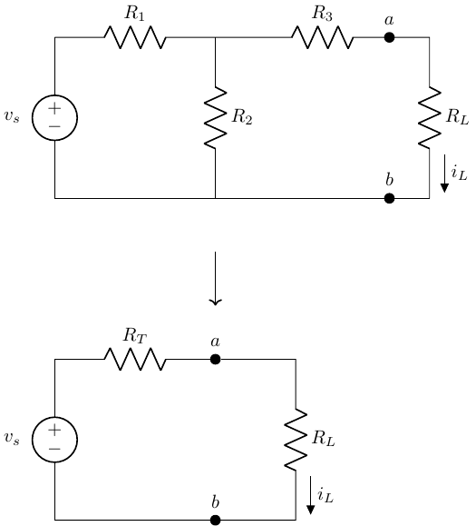
Are these equivalent?
Let’s convince ourselves that \(i_L\) is the same for both circuits…
Another example…
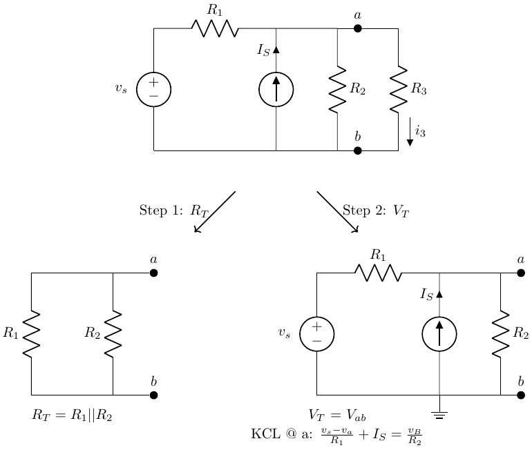
Norton Equivalent Sources
Norton Theorem
When a circuit is viewed from the perspective of the load, any source network composed of ideal voltage/current sources and linear resistors (i.e., defined by Ohm’s law), can be replaced by an equivalent circuit with:
An ideal current source (\(V_T\)), in parallel with
An equivalent resistance (\(R_N = R_T\)).
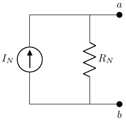
Step 2: Calculate the Norton Equivalent Source
Similar to calculating the Thevenin equivalent source, but instead of solving for the open-circuit voltage at the terminals, solve for the short circuit current at the terminals.
This short circuit current is the Norton source current (\(I_N\)).
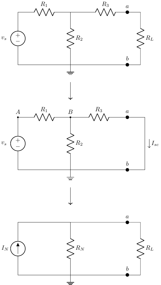
Source Transformation Example
Now a simple current divider!
\[ i_4 = \left( \frac{v_1}{R_1} - I_S - \frac{v_s}{R_3} \right) \left[ \frac{\frac{1}{R_4}}{\frac{1}{R_1} + \frac{1}{R_2} + \frac{1}{R_3} + \frac{1}{R_4}}\right] \]
Maximum Power Transfer
We can use our “simple” Thevenin equivalent circuit to now represent any source:load combination.

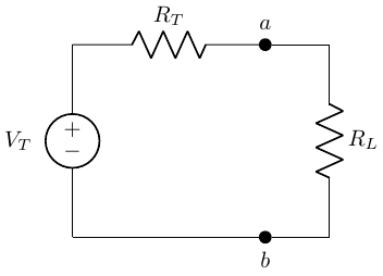
Power Maximum Transfer Condition
What load resistance allows us to deliver the most power to the load?