Operational Amplifiers (Op-Amps)
BME253L - Fall 2025
November 3, 2025
Ideal Op-Amp Model
An ideal op-amp has the following characteristics:
Infinite open-loop gain (A → ∞)
Infinite input impedance (\(Z_{in}\) → ∞)
Zero output impedance (\(Z_{out}\) = 0)
Infinite bandwidth (no frequency dependence)
Zero offset voltage (output is zero when inputs are equal)
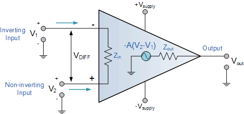
- In practical applications, real op-amps deviate from these ideal characteristics, but the ideal model provides a useful approximation for analysis.
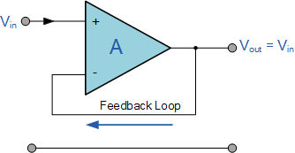
Buffer / Voltage Follower
A buffer, or voltage follower, is a configuration where the output voltage directly follows the input voltage.
It is used to isolate different stages of a circuit, preventing loading effects and ensuring signal integrity.
The voltage follower has a gain of 1 (unity gain) and provides high input impedance and low output impedance.
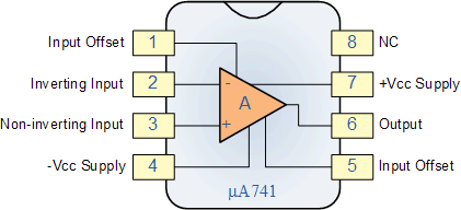
Op-Amp Chip Pinout
Inverting Amplifier

Using negative feedback, the op-amp adjusts \(V_{out}\) to make \(V_+ = V_-\).
Since \(V_+ = 0V\) (grounded), \(V_- = 0V\).
Using Ohm’s Law and Kirchhoff’s Current Law (KCL):
\(I_{in} = \frac{V_{in} - V_-}{R_{in}} = \frac{V_{in}}{R_{in}}\)
\(I_{f} = \frac{V_- - V_{out}}{R_f} = \frac{-V_{out}}{R_f}\)
Since \(I_{in} = I_{f}\) (no current into op-amp input):
\[ \begin{gather} \frac{V_{in}}{R_{in}} = \frac{-V_{out}}{R_f} \\ \frac{V_{out}}{V_{in}} = -\frac{R_f}{R_{in}} \end{gather} \]
Gain is controlled by the ratio of resistors (until saturation).
The negative sign indicates a 180-degree phase shift between input and output.
Non-Inverting Amplifier

Using negative feedback, the op-amp adjusts \(V_{out}\) to make \(V_+ = V_-\).
Since \(V_+ = V_{in}\), \(V_- = V_{in}\).
Using Ohm’s Law and Kirchhoff’s Current Law (KCL):
\(I_{f} = \frac{V_- - V_{out}}{R_f} = \frac{V_{in} - V_{out}}{R_f}\)
\(I_{g} = \frac{V_{-} - 0V}{R_g} = \frac{V_{in}}{R_g}\)
Since \(I_{f} = I_{g}\) (no current into op-amp input):
\[ \begin{gather} \frac{V_{in} - V_{out}}{R_f} = \frac{V_{in}}{R_g} \\ \frac{V_{out}}{V_{in}} = 1 + \frac{R_f}{R_g} \end{gather} \]
Gain is controlled by the ratio of resistors plus one (until saturation).
The output is in phase with the input.
Summing Amplifier
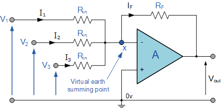
Using negative feedback, the op-amp adjusts \(V_{out}\) to make \(V_+ = V_-\).
Since \(V_+ = 0V\) (grounded), \(V_- = 0V\).
Using Ohm’s Law and Kirchhoff’s Current Law (KCL):
\(I_{1} = \frac{V_{in1} - V_-}{R_{1}} = \frac{V_{in1}}{R_{1}}\)
\(I_{2} = \frac{V_{in2} - V_-}{R_{2}} = \frac{V_{in2}}{R_{2}}\)
\(I_{f} = \frac{V_- - V_{out}}{R_f} = \frac{-V_{out}}{R_f}\)
Since \(I_{1} + I_{2} = I_{f}\) (no current into op-amp input):
\[ \begin{gather} \frac{V_{in1}}{R_{1}} + \frac{V_{in2}}{R_{2}} = \frac{-V_{out}}{R_f} \\ V_{out} = -R_f \left( \frac{V_{in1}}{R_{1}} + \frac{V_{in2}}{R_{2}} \right) \end{gather} \]
Note
The output voltage is the negative weighted sum of the input voltages.
Differential Amplifier
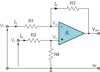
Using negative feedback, the op-amp adjusts \(V_{out}\) to make \(V_+ = V_-\).
Using Ohm’s Law and Kirchhoff’s Current Law (KCL):
For the non-inverting input:
\[ V_+ = V_2 \frac{R_4}{R_2 + R_4} \]
For the inverting input:
\[ \begin{gather} I_1 = I_f \\ \frac{V_1 - V_-}{R_1} = \frac{V_- - V_{out}}{R_3} \\ \end{gather} \]
If we set \(R_1 = R_2\) and \(R_3 = R_4\), solving for \(V_{out}\):
\[ V_{out} = \frac{R_3}{R_1} (V_2 - V_1) \]
Note
The output voltage is the amplified difference between the two input voltages.
Active Low-Pass Filter
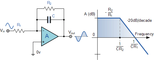
D.C. Gain: \(\frac{-R_2}{R_1}\)
A.C. Gain: \(\frac{-R_2}{R_1} \frac{1}{1+\omega R_2 C}\)
Cutoff Frequency: \(\omega_c = \frac{1}{R_2 C}\)
Active High-Pass Filter

Active Band-Pass Filter
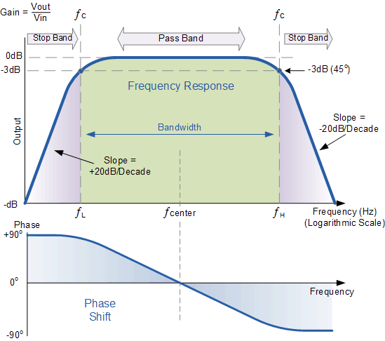
D.C. Gain: \(\frac{-R_2}{R_1}\)
\(\omega_{HP} = \frac{1}{R_1 C_1}\)
\(\omega_{LP} = \frac{1}{R_2 C_2}\)
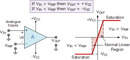
Comparator
A comparator is a device that compares two voltages or currents and outputs a digital signal indicating which is larger.
It lacks negative feedback, resulting in a high gain that drives the output to saturation.
Comparator with Hysteresis (Schmitt Trigger)
