Zephyr: Pulse Width Modulation
BME554L - Spring 2026
Overview
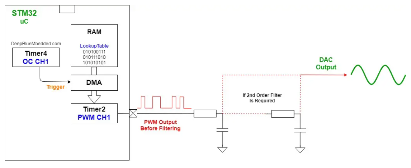
- Most microcontrollers and SoCs do not have a native DAC.
- Much easier to output digital
HIGHorLOWsignals. - Timing and duty cycle (pulse width) of
HIGHandLOWsignals can be used to approximate an analog voltage. - LPF to smooth out the PWM signal.
PWM Signal Generation
Block Diagram
Common Uses
- Adjust LED brightness
- Control motor speed
- Control servo motor direction
- Analog output
- Data encoding
Project Setup
prj.conf
CONFIG_PWM=y
Devicetree
- There are multiple PWM timers (controllers) on the nRF52833.
- Each PWM timer has multiple channels.
- Zephyr has a “compatibility” label called
pwm-leds.
aliases = {
    pwm1 = &pwmch1;
    pwm2 = &pwmch2;
};
pwm {
    compatible = "pwm-leds";
    pwmch1: pwm_1 {
        pwms = < &pwm0 0 PWM_MSEC(1) PWM_POLARITY_NORMAL>;  // 0 - channel
        label = "PWM_CH1";
    };
    pwmch2: pwm_2 {
        pwms = < &pwm0 1 PWM_MSEC(1) PWM_POLARITY_NORMAL>; // 1 - channel
        label = "PWM_CH2";
    };
};
Configure the controller(s)
&pwm0 {
    compatible = "nordic,nrf-pwm";
    reg = <0x4001c000 0x1000>;
    interrupts = <28 NRF_DEFAULT_IRQ_PRIORITY>;
    status = "okay";
    #pwm-cells = <3>;
    pinctrl-0 = <&pwm0_default>;
    pinctrl-1 = <&pwm0_sleep>;
    pinctrl-names = "default", "sleep";
};
Use pinctrl to configure IO behavior for non-GPIO pins.
&pinctrl {
    compatible = "nordic,nrf-pinctrl";
    status = "okay";
    pwm0_default: pwm0_default {
        group1 {
            psels = <NRF_PSEL(PWM_OUT0, 0, 28)>, // P0.28, channel 0
                    <NRF_PSEL(PWM_OUT1, 0, 30)>; // P0.30, channel 1
            nordic,invert;
        };
    };
    pwm0_sleep: pwm0_sleep {
        group1 {
            psels = <NRF_PSEL(PWM_OUT0, 0, 28)>, // P0.28, channel 0
                    <NRF_PSEL(PWM_OUT1, 0, 30)>; // P0.30, channel 1
            low-power-enable;
        };
    };
};
Main Code
// load in the Zephyr library
#include <zephyr/drivers/pwm.h>

// define structs based on DT aliases
static const struct pwm_dt_spec pwm1 = PWM_DT_SPEC_GET(DT_ALIAS(pwm1));
static const struct pwm_dt_spec pwm2 = PWM_DT_SPEC_GET(DT_ALIAS(pwm2));

// check that the PWM controller is ready
if (!pwm_is_ready_dt(&pwm1))  {
    LOG_ERR("PWM device is not ready.");
    return -ENODEV;
}

// set the PWM duty cycle (pulse length)
err = pwm_set_pulse_dt(&pwm1, pwm1.period/2); // 50% duty cycle (be careful with integer division)
if (err) {
    LOG_ERR("Could not set pwm1 driver [%d].", err);
    // maybe change to an ERROR state
}
Changing PWM Duty Cycle
The pulse length (duty cycle) can be changed “on the fly”, but only changes at the next period.
Can be done with a timer or triggered by an event or poll signal.
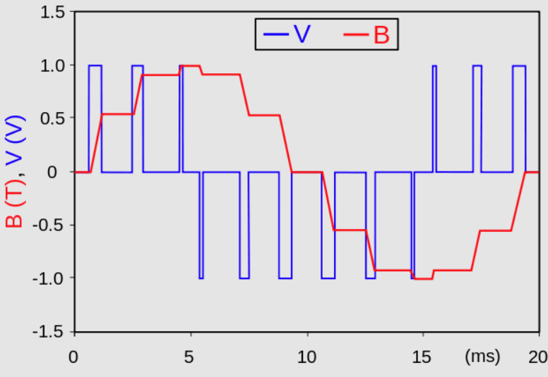
How to Sinusoidally Module LED Brightness Using a PWM
Change the duty cycle of the PWM signal at a known timing interval. Can be done with a timer, callback function run at a set interval (e.g., ADC async), etc.
Need to consider how often to update based on frequency content of the desired output signal.
PWM clock frequency should be much higher than the output signal frequency.
LPF to smooth out PWM clock frequency-based transitions.
Lower-Level nRF PWM Control
https://docs.nordicsemi.com/bundle/ps_nrf52833/page/pwm.html

Resources
- Zephry: PWM
- Pulse Width Modulation
- Zephyr: Blinky Sample
- Sine Wave Generation
- Nordic Semiconductor: PinCtrl
- Nordic DevAcademy: PWM