Zephyr: Pulse Width Modulation

BME554L -Fall 2025 - Palmeri

Dr. Mark Palmeri, M.D., Ph.D.

Duke University

Invalid Date

Overview

  • Most microcontrollers and SoCs do not have a native DAC.
  • Much easier to output digital HIGH or LOW signals.
  • Timing and duty cycle (pulse width) of HIGH and LOW signals can be used to approximate an analog voltage.
  • LPF to smooth out the PWM signal.

sine-from-pwm

PWM Signal Generation

Nordic DevAcademy: PWM

Block Diagram

sine-from-pwm-block-diagram

Common Uses

  • Adjust LED brightness
  • Control motor speed
  • Control servo motor direction
  • Analog output
  • Data encoding

Project Setup

prj.conf

CONFIG_PWM=y

Devicetree

  • There are multiple PWM timers (controllers) on the nRF52833.
  • Each PWM timer has multiple channels.
  • Zephyr has a “compatibility” label called pwm-leds.
aliases = {
    pwm1 = &pwmch1;
    pwm2 = &pwmch2;
};
pwm {
    compatible = "pwm-leds";
    pwmch1: pwm_1 {
        pwms = < &pwm0 0 PWM_MSEC(1) PWM_POLARITY_NORMAL>;  // 0 - channel
        label = "PWM_CH1";
    };
    pwmch2: pwm_2 {
        pwms = < &pwm0 1 PWM_MSEC(1) PWM_POLARITY_NORMAL>; // 1 - channel
        label = "PWM_CH2";
    };
};

Configure the controller(s)

&pwm0 {
    compatible = "nordic,nrf-pwm";
    reg = <0x4001c000 0x1000>;
    interrupts = <28 NRF_DEFAULT_IRQ_PRIORITY>;
    status = "okay";
    #pwm-cells = <3>;
    pinctrl-0 = <&pwm0_default>;
    pinctrl-1 = <&pwm0_sleep>;
    pinctrl-names = "default", "sleep";
};

Use pinctrl to configure IO behavior for non-GPIO pins.

&pinctrl {
    compatible = "nordic,nrf-pinctrl";
    status = "okay";
    pwm0_default: pwm0_default {
        group1 {
            psels = <NRF_PSEL(PWM_OUT0, 0, 28)>, // P0.28, channel 0
                    <NRF_PSEL(PWM_OUT1, 0, 30)>; // P0.30, channel 1
            nordic,invert;
        };
    };
    pwm0_sleep: pwm0_sleep {
        group1 {
            psels = <NRF_PSEL(PWM_OUT0, 0, 28)>, // P0.28, channel 0
                    <NRF_PSEL(PWM_OUT1, 0, 30)>; // P0.30, channel 1
            low-power-enable;
        };
    };
};  

Main Code

// load in the Zephyr library
#include <zephyr/drivers/pwm.h>

// define structs based on DT aliases
static const struct pwm_dt_spec pwm1 = PWM_DT_SPEC_GET(DT_ALIAS(pwm1));
static const struct pwm_dt_spec pwm2 = PWM_DT_SPEC_GET(DT_ALIAS(pwm2));

// check that the PWM controller is ready
if (!device_is_ready(pwm1.dev))  {
    LOG_ERR("PWM device %s is not ready.", pwm1.dev->name);
    return -1;
}

// set the PWM duty cycle (pulse length)
err = pwm_set_pulse_dt(pwm1, pwm1->period/2); // 50% duty cycle
if (err) {
    LOG_ERR("Could not set pwm1 driver.");
}

Changing PWM Duty Cycle

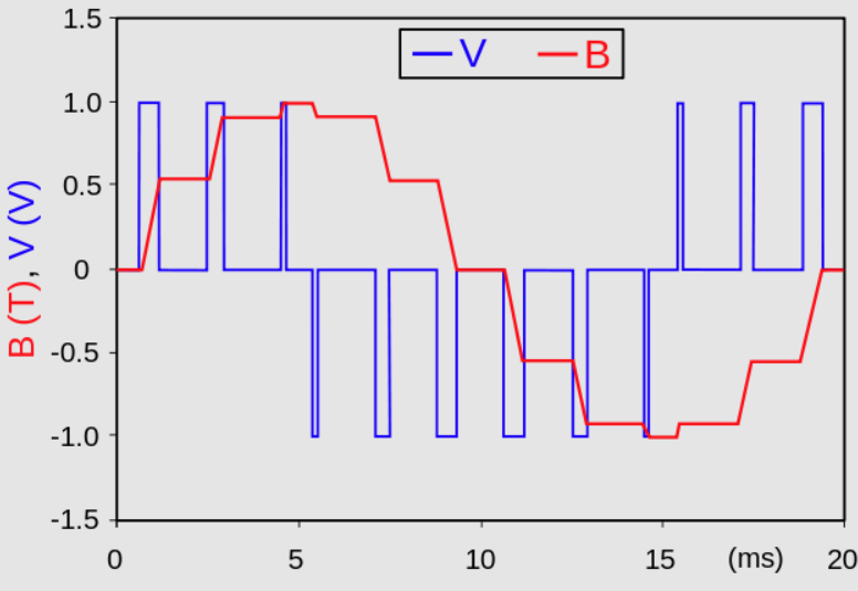
  • The pulse length (duty cycle) can be changed “on the fly”, but only changes at the next period.
  • Can be done with a timer or event-driven.

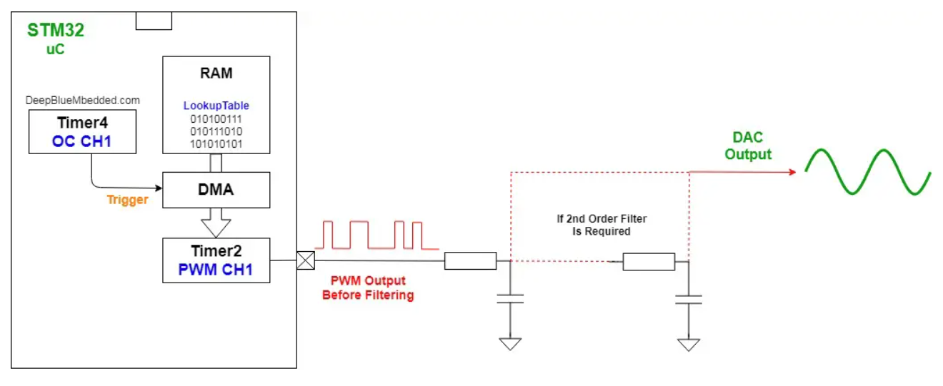
How to Sinusoidally Module LED Brightness Using a PWM

  • Use a timer to change the duty cycle of the PWM signal. How often?
  • Set PWM counter period to ???
  • LPF

Resources