Event-Driven State Machine
BME554L - Spring 2026
Introduction
- Nested conditional logic main loops are hard to read and maintain.
- State machines are a common way to implement complex logic.
- States have transitions that are triggered by events or conditions.
- States can have entry / exit routines that are executed when the state is entered / exited.
- The “run” status of a state is commonly referred to as the “state machine tick” and recurrently loops.
- State diagrams are used to visualize state machines.
- State structures are used to capture variables associated with describing the state.
In-Class Demo
- You (and your daily routine)
- What are your “states”?
- What are your “events”?
- ICD
Implementation
State Diagram
- Generating the state diagram is the first step in implementing a state machine.
- Usually start with “pencil and paper” to sketch out the states and transitions.
- Consider the following:
- What are the states?
- What are the transitions?
- What are the events that trigger transitions?
- What are the entry / exit routines for each state?
- UML (Universal Modeling Language) is a common way to represent state diagrams.
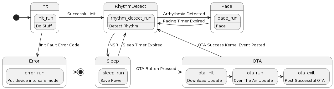
PlantUML Example
@startuml

[*] -> Init

state Init {
    init_run: Do Stuff
}

state RhythmDetect {
    rhythm_detect_run: Detect Rhythm
}

state Sleep {
    sleep_run: Save Power
}

state Pace {
    pace_run: Pace
}

state OTA {
    ota_init: Download Update
    ota_init -> ota_run
    ota_run: Over The Air Update
    ota_run -> ota_exit
    ota_exit: Post Successful OTA
}

state Error {
    error_run: Put device into safe mode
}

Init -> RhythmDetect : Successful Init
Init -d-> Error : Init Fault Error Code
RhythmDetect -> Pace : Arrhythmia Detected
Pace -> RhythmDetect : Pacing Timer Expired
RhythmDetect -d-> Sleep : NSR
Sleep -> RhythmDetect: Sleep Timer Expired
Sleep -> OTA : OTA Button Pressed
OTA -> RhythmDetect : OTA Success Kernel Event Posted
Error -> [*]

@enduml
Kernel Events
- What is a “kernel”?
- The part of the RTOS that interacts with hardware.
- Kernel events can be used to indicate that “something” has happened, which may dictate the function of the state machine.
- Button press
- Sensor crossing a threshold
- Timer expiring
- When an event occurs, it triggers an Interupt Service Routine (
ISR), which calls a callback function.
Code: Switch-Case
- The simplest implementation of a state machine is a switch-case statement.
- The switch statement is used to select the current state.
- The case statements are used to implement the logic for each state.
- Cases can be nested to implement sub-states.
- Enumerations can be used to give states verbose names instead of numbers.
- The break statement is used to exit the switch statement.
- The default statement is used to handle unexpected states.
Pseudo-Code
enum device_states { init, run, sleep };

int device_state = init; // initialize state

/* structure to bookkeep state variables */
struct device_state_vars {
    int var1;
    int var2;
};

while (1) {
    switch (device_state) {
        case init:
            /* do stuff to initialize device */
            device_state = run; // change the state
            break;  // exit the switch statement
        case run:
            /* run device */
            if (condition) {
                device_state = sleep;
            }
            break;
        case sleep:
            /* sleep device */
            if (condition) {
                device_state = run;
            }
            break;
        default:
            /* handle unexpected state */
            break;
    }
}
The switch-case approach loses some of its elegance when there are many states and many transitions and states have entry / exit routines.
Resources
- DigiKey: How to Program and Arduino Finite State Machine
- Instructables: Finite State Machine on an Arduino