Event-Driven State Machine
BME254L - Spring 2026
Event-Driven State Machine
Introduction
Nested conditional logic main loops are hard to read and maintain.
State machines are a common way to implement complex logic.
States have transitions that are triggered by events or conditions.
States can have entry / exit routines that are executed when the state is entered / exited.
The “run” status of a state is commonly referred to as the “state machine tick” and recurrently loops.
State diagrams are used to visualize state machines.
State structures are used to capture variables associated with describing the state.
In-Class Demo
- You (and your daily routine)
- What are your “states”?
- What are your “events”?
- ICD
Implementation
State Diagram
Generating the state diagram is the first step in implementing a state machine.
Usually start with “pencil and paper” to sketch out the states and transitions.
Consider the following:
What are the states?
What are the transitions?
What are the events that trigger transitions?
What are the entry / exit routines for each state?
UML (Universal Modeling Language) is a common way to represent state diagrams.
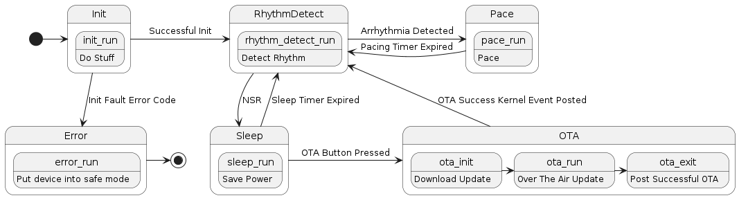
PlantUML Example
@startuml

[*] -> Init

state Init {
    init_run: Do Stuff
}

state RhythmDetect {
    rhythm_detect_run: Detect Rhythm
}

state Sleep {
    sleep_run: Save Power
}

state Pace {
    pace_run: Pace
}

state OTA {
    ota_init: Download Update
    ota_init -> ota_run
    ota_run: Over The Air Update
    ota_run -> ota_exit
    ota_exit: Post Successful OTA
}

state Error {
    error_run: Put device into safe mode
}

Init -> RhythmDetect : Successful Init
Init -d-> Error : Init Fault Error Code
RhythmDetect -> Pace : Arrhythmia Detected
Pace -> RhythmDetect : Pacing Timer Expired
RhythmDetect -d-> Sleep : NSR
Sleep -> RhythmDetect: Sleep Timer Expired
Sleep -> OTA : OTA Button Pressed
OTA -> RhythmDetect : OTA Success Kernel Event Posted
Error -> [*]

@enduml
In-Class / Lab Exercise
Event-Driven State Machine Lab Exercise (Kitchen Timer)