Computer Aided Design (CAD) with Onshape
BME254L - Spring 2026
Computer Aided Design (CAD) with Onshape
Why CAD?
Formally capture 2D projection sketches → 3D parts.
Dimension consistency checks.
Assemble multiple parts to check fit, interfaces and simulate stress/strain/movement.
Translate to physical realization (e.g., 3D print, mil).
General technical drawings for manufacturing.
Capture design history, while facilitating iteration / change.
Onshape
![]()
We will be using Onshape, a cloud-based CAD package with a similar workflow to SolidWorks.
You will receive an email notification about being added to Duke’s Onshape instance: https://duke.onshape.com
This is a specific Duke instance of Onshape, not the public one (https://onshape.com). Your Duke account creation will also automatically trigger an account being created in the non-Duke system too, but you cannot share projects between the two instances, so please make sure that you are using the Duke version for coursework!!

General Workflow
Sketch 2D profiles (dimensioned).
Use dimensions to size parts / features.
Use constraints to align sketch features to one another (avoid over constraining!).
Use contruction lines to help with sketching.
Extend 2D profiles to 3D parts.
Extrude (new, add, subtract, intersection)
Revolve
Utilize symmetry to mirror operations
Modify 3D parts
Fillet/chamfer edges
Hole tool
Combine common modifications into single step
Utilize “patterns” to repeat modifications
Assemble multiple parts.
Create mechanical drawings for machining / documentation.
Tips
Utilize part symmetry and patterns to reduce manual effort.
Define new sketch planes on part references that “make sense”.
Practice!!
There are many ways to create the same parts.
Some are more amenable to future modification than others; those aren’t always the fastest to create from scratch.
Experience is highly valuable on a resume.
Mechanical Design Considerations
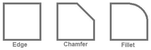
Modifying Edges / Corners
Fillet - rounded edge/corner
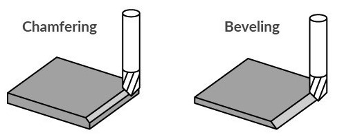
Chamfer - sloped / angled corner / edge
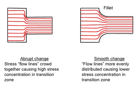
Why modify edges?
Reduce stress concentrations (fillet > chamfer)
Reduce sharp edges
Ease assembly (potentially at a cost to manufacturing)
Type of Holes
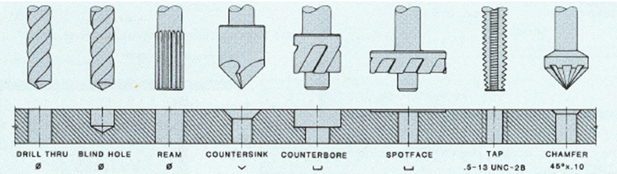
CAD tools have Hole tools that can be very useful.
Hole diameter (and threading) can be specified by ANSI (e.g., #10-32, 32 tpi) or ISO (e.g., M5-0.8, mm pitch) standards
Mechanical drawings typically consistent of a table of holes (that can be automatically generated when using the Hole tool)
Mechanical Drawings
Multiview / orthographic projection
ISO 8015: Geometrical product specifications (GPS) — Fundamentals — Concepts, principles and rules
Dimension callouts / values should not overlap any part lines!
Design For Manufacturing (DFM) (and beyond)
Purpose
Protection (e.g., water, debris, sunlight)
Supporting relative position
Mounting
Loading
Shipping
Gravity / Momentum
Falls (especially corners!)
Buttons / Dials / Sliders
Interfaces
Cables
Displays
Buttons
Minimize everything else to save on time and cost!
Subtractive vs. Additive Manufacturing
Machining (subtractive)
Milling
Turning
Drilling
Grinding
Additive
3D Printing
Laser Sintering
Stereolithography
In-Class Demo
Give operations meaningful names
Use variables for dimensions that may change