Switched, Series & Parallel Resistance
BME253L - Fall 2025
September 3, 2025
Analyzing Switched Resistive Circuit
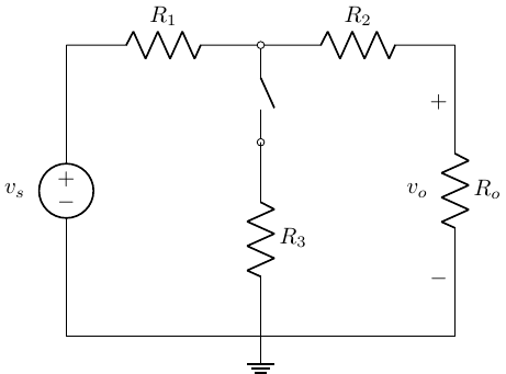
Given:
- \(v_s\) = 300 V
- \(R_1\) = 100 \(\Omega\)
- \(R_2\) = 100 \(\Omega\)
- \(R_3\) = 200 \(\Omega\)
- \(R_o\) = 100 \(\Omega\)
Find \(v_o\) with both the switch open and closed.
We will start with the switch open case…
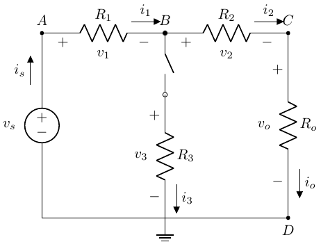
Step 1: Assign & Label Nodes, Voltage References & Currents
Important
Use the (+) sign convention!
What does the open switch mean?
Tip
An open switch means no current can flow through \(R_3\)!
Step 2: KVL & KCL
KVL
\(D \rightarrow A \rightarrow B \rightarrow C \rightarrow D\)
\(-v_s + v_1 + v_2 + v_o = 0\)
KCL
\(A: i_s = i_1\)
\(B: i_1 = i_2\)
\(C: i_2 = i_o\)
So, \(i_s = i_1 = i_2 = i_o\)
Tip
This is one, closed-path loop!
Step 1: Assign & Label Nodes, Voltage References & Currents

Step 2: KVL & KCL
KVL
\(D \rightarrow A \rightarrow B \rightarrow C \rightarrow D\)
- \(-v_s + v_1 + v_2 + v_o = 0\)
\(D \rightarrow A \rightarrow B \rightarrow D\)
- \(-v_s + v_1 + v_3 = 0\)
\(D \rightarrow B \rightarrow C \rightarrow D\)
- \(-v_3 + v_2 + v_0 = 0\)
KCL
\(A: i_s = i_1\)
\(B: i_1 = i_2 + i_3\)
\(C: i_2 = i_o\)
\(D: i_3 + i_o = i_s\)
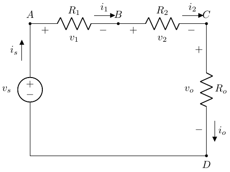
Let’s take a look at that open switch example…
Remember that \(i_s = i_1 = i_2 = i_o\)
- \(R_1\) is in series with \(R_2\), which is in series with \(R_o\); they are all in series with one another!
Remember applying KVL:
\(v_s = i_s \left(R_1 + R_2 + R_o\right)\).
This looks like Ohm’s law for a single resistor (\(R_{eq}\)): \(v_s = i_s R_{eq}\), where:
\(R_{eq} = R_1 + R_2 + R_o\)
Series Resistance
- If \(R_1, R_2, ... R_N\) are in series, then \(i_{R_1} = i_{R_2} = ... i_{R_N}\), which means:
\[ R_{eq} = \Sigma_{n=1}^N R_n \]
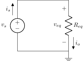
- Why is this useful? Way easier to solve for \(i_o\) in this case; it is just Ohm’s Law!
Voltage Division
What do series resistors do to a source voltage?
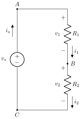
\(KVL: -v_s + v_i + v_2 = 0\)
\(KCL_{B}: i_1 = i_2\)
\(v_s = R_1 i_1 + R_2 i_1\)
\(i_1 = \frac{v_s}{R_1 + R_2}\)
\(v_1 = i_1 R_1 = v_s \frac{R_1}{R_1 + R_2}\)
\(v_2 = i_2 R_2 = v_s \frac{R_2}{R_1 + R_2}\)
Important
Series resistors divide voltage in proportion to \(\frac{R_n}{R_{eq}}\)!
Parallel Resistance Circuits
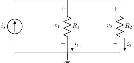
\(R_1\) & \(R_2\) share common nodes and have the same voltage drop across them, so they are in parallel.
KCL: \(i_s = i_1 + i_2\)
KVL: \(-v1 + v_2 = 0 \rightarrow v_1 = v_2\)
Ohm’s Law: \(i_1 = \frac{v_1}{R_1}\) and \(i_2 = \frac{v_2}{R_2} = \frac{v_1}{R_2}\)
Current Divider
Question?
What is the “fastest” way to solve for \(v_1\)?
What about \(i_1\) and \(i_2\)?
\[ \begin{align} i_1 & = \frac{v_1}{R_1} = \frac{i_S R_{eq}}{R_1} = i_S \frac{\frac{1}{R_1}}{\frac{1}{R_1} + \frac{1}{R_2}} \\ i_1 & = i_S \left(\frac{R_2}{R_1+R_2}\right) \\ i_2 & = i_S - i_1 \\ i_2 & = i_S \left( \frac{R_1}{R_1 + R_2} \right) \end{align} \]
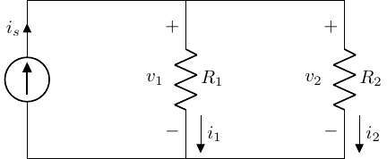
Note
The current in one branch is proportional to its conductance, which is proportional to the resistance in the alternate branch(es)!
Lets look at the limiting cases…
If \(R_2 \rightarrow 0\), then \(i_i \rightarrow 0\). In other words, current flows to the path of least (in this case, no) resistance.
If \(R_2 \rightarrow \infty\), then \(i_1 \rightarrow i_S\).