Ohm’s & Kirchoff’s Laws, Resistive Loads and Meters
BME253L - Fall 2025
August 27, 2025
Sources provide energy to a circuit (\(P < 0\)).
Loads consume energy from a circuit (\(P > 0\)).
Postive power is when postive current flows from \((+) -> (-)\) voltage drop across a circuit element:

Power Source/Load Example
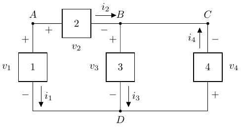
Given:
\[ \begin{gather} P_1 = -100 W \\ P_2 = 50 W \\ P_3 = 30 W \\ v_1 = 10 V \\ v_2 = 5 V \\ i_3 = 6 A \end{gather} \]
We don’t know what these circuit components are, but given power/voltage/current associated with them, we can determine if they are sources or loads, and solve for the unknown quantities.
Circuit Element 1
- Source or load?
- Solve for \(i_1\): \[ \begin{gather} P_1 = v_1 i_1 \\ -100 W = 10 V (i_1) \\ i_1 = -10 A \end{gather} \]
- Element 1 is a source!
Circuit Element 2
- Source or load?
- Solve for \(i_2\): \[ \begin{gather} P_2 = v_w i_2 \\ 50 W = 5 V (i_2) \\ i_2 = 10 A \end{gather} \]
- Element 2 is a load!
Parallel Devices
Devices in parallel have the same voltage difference across them:
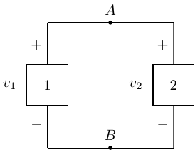
\[ v_1 = v_2 \]
Serial Devices
Devices in series have the same current flowing through them.
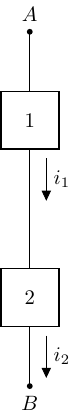
\[ i_1 = i_2 \]
Resistive Loads
- Resistors are dissipative loads (typically as heat).
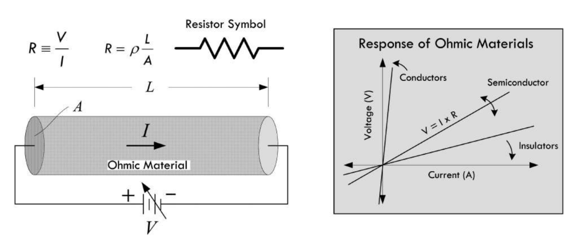
Conductive wire before/after the resistor element is considered “ideal” (non-dissipative).
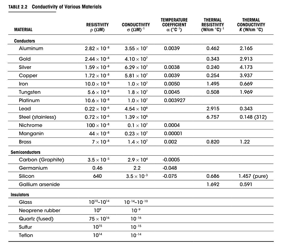
\(\rho_{carbon} = 3.5 \times 10^{-5} \Omega \cdot m\)
Conductivity of Materials
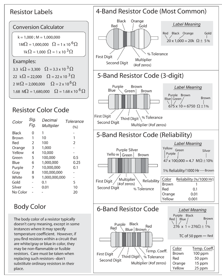
Ceramic Resistor Labeling
Switches
Switches are mechanical devices that interrupt or divert current flow in a circuit.
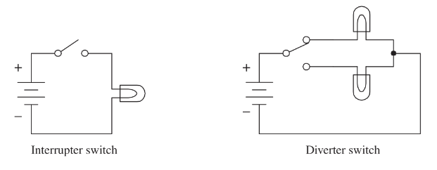
Open interrupter switches create an open circuit:
\(R \rightarrow \infty\)
\(i = 0\) (regardless of \(v\), to a point)
Closed interrupter switches create a short circuit:
\(R = 0\)
\(v = 0\) (regardless of \(i\))
\(P_{open} = 0 = P_{short}\) (why?)
Ideal Sources
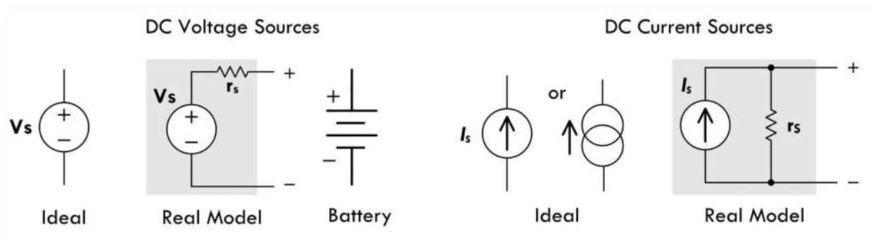
For an ideal voltage source, the source current is a function of the attached circuit resistance.
For an ideal current course, the source voltage is a function of the attached circuit resistance.
“Real” Source
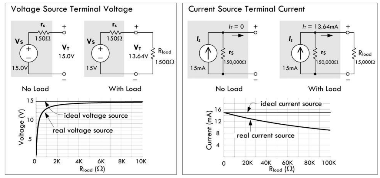
Real sources have internal resistance.
Ideally:
Internal resistance of a voltage source \(\rightarrow 0\).
Internal resistance of a current source \(\rightarrow \infty\).
Why?
Tip
Think KCL and KVL…
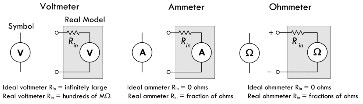
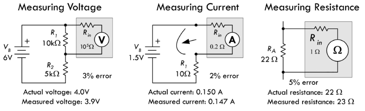
Measuring Voltage, Current & Resistance